All turbocharged engines have some form of factory boost control, all of which work on a pneumatic system. To understand how a boost controller works, we must first look at this system. Ultimately, the boost pressure is determined by the wastegate, which on most factory turbos, is integrated into the exhaust (turbine) housing. The purpose of the wastegate is to dump a controlled amount of exhaust gas from the exhaust before the turbine to keep the turbo shaft speed, and therefore the boost, under control. If not for the wastegate, the boost pressure would continue to rapidly rise to disastrous levels.
How does a Boost Controller work?
The wastegate actuator, which is the can shaped object mounted on the turbo (except on external wastegate systems), forms part of the pneumatic system which controls the wastegate. Boost pressure is delivered to the actuator via a small hose from the compressor outlet, thus forming a control loop. As the boost pressure rises, this pressure begins to open the wastegate via the actuator to slow the build-up of boost until the set level is reached.
Raising the boost:
The power produced by a turbocharged engine is (in perfect conditions) directly related to the amount of air that fills the cylinders. In practice, other variables such as temperature, humidity, ignition timing etc make it a less-than-direct relationship. That aside, raising the boost pressure is a very simple and effective way of increasing the amount of airflow into the engine, thereby increasing the power output.
Cautions: While increasing the boost is a very easy way of extracting power, it should be done sensibly and with a little appreciation of the mechanical limits of the engine. Therefore, it is important to use a boost gauge and make small increments. Raising boost levels will increase the amount of mechanical and thermal stress on all engine components, however, in most applications boost increases of 10-20% are quite safe. Also be aware that any engine components that may fail as a result of careless adjustment are not likely to be warranted by the manufacturer.
Increasing the boost:
Here’s where the GFB boost controller comes in. When plumbed correctly into the hose that feeds the wastegate actuator, the controller “bleeds off” a measured amount of air (set by the adjusting screw on the top) to reduce the pressure in the hose. This sends a lower boost signal to the actuator, so that the wastegate will remain closed for longer, thus increasing the boost level. The end result is that the turbo is producing more boost, but the wastegate doesn’t know!
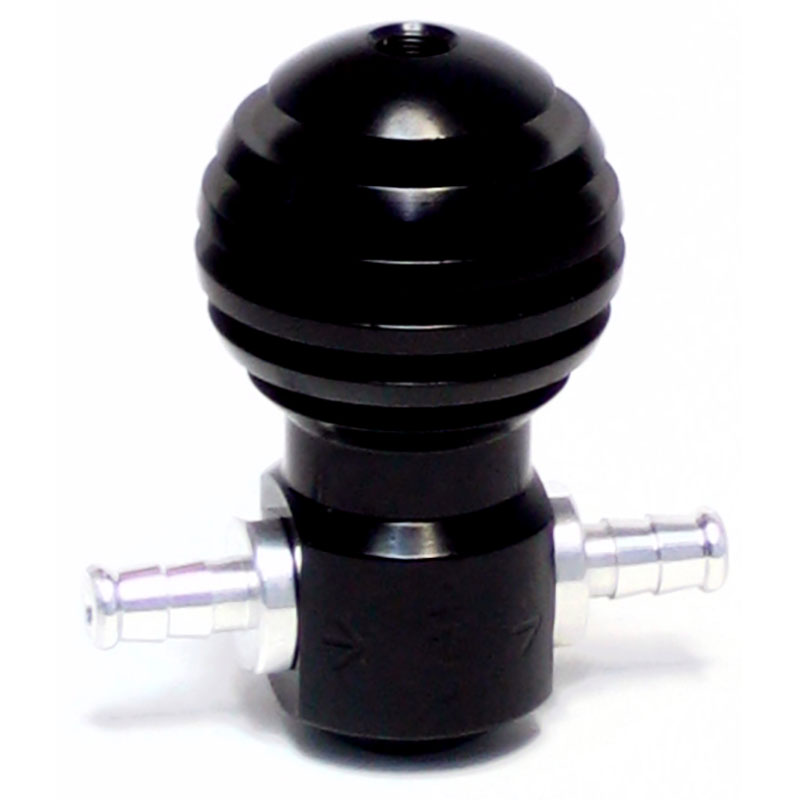
Ball-and-spring, or bleed type? Many other manufacturers use what is described as ball-and-spring, or “gated” type boost controllers. The claim is that pressure is held back from the wastegate to prevent it from opening prematurely, and only allowing pressure in once the boost level is almost reached. Whilst this sounds good in theory, in practice it does not always work.
Bleed type:
GFB boost controllers are all bleed-style, which uses a restrictor (a small precision hole in the pressure inlet nipple) and a taper needle adjustment. The restrictor plays a very important role, which must not be underestimated. Basically, without the restrictor, the adjustment needle would not be able to bleed off enough air to lower the pressure reaching the wastegate actuator.
The turbo is pumping more than enough air to overcome such a small bleed. By placing a restrictor in the flow path, with the bleed on the other side, the air cannot pass fast enough to overcome the bleed, therefore the pressure will drop at the actuator and boost will rise. This explains why if you install the controller backwards, you will not be able to raise the boost.
The diameter of the restrictor hole is very critical, and the wrong size can affect spool-up, or cause boost spikes. GFB has spent a lot of time and development ensuring the restrictor is optimum, and the results show.
Ball-and-spring types:
These controllers still use a bleed, but the most common technique is to place a steel ball behind the restrictor hole, held shut by a spring. The main problem with this technique is that since the restrictor hole is so critical to boost, placing a free-floating ball behind it adversely affects its performance. Because the ball is free-floating, it can act like a pea in a referee’s whistle, fluttering around in the restrictor hole. This then causes boost fluctuations, and (if the spring is set incorrectly) boost spikes. This is much easier to see on a dyno which accurately logs boost pressure.